Characterization of Dispersion Relations
Research supported by:
JPL's Innovative Spontaneous Concepts,
JPL's Strategic University Research Partnership, and
the Princeton Plasma Physics Laboratory's Program in Plasma Science and Technology
Motivation
Numerical and experimental tools for plasma dispersion relation studies in plasma propulsion devices are an important resource for researchers investigating thruster physics. The plasma wave modes described by the dispersion relation can affect physical processes such as particle transport or grow into instabilities that disrupt the discharge. For example, the experimentally observed anomalous electron transport in the channel of Hall thrusters might be partly explained by electrostatic plasma waves influencing transport processes. A core aspect of such plasma wave studies involves characterizing the plasma dispersion relation, which requires the development of versatile numerical and experimental tools.
The Dispersion Relation
The dispersion relation \(\mathcal{D}\) of a plasma is a function which satisfies the condition \[ \mathcal{D}(\omega, \mathbf{k}; p_1, p_2, \dots ) = 0, \] where \(\omega\) is the wave frequency, \(\mathbf{k}\) is the wavenumber vector, and the \(p_i\) are plasma parameters such as electron density or background magnetic field. The exact functional form of \(\mathcal{D}\) depends on the particular plasma model and governing equations from which it is derived. The plasma wave modes that may arise in a discharge are described by the complex zeros of \(\mathcal{D}\), expressed as functions of the form \(\omega = \omega(\mathbf{k};p_1, p_2, \dots)\) derived by solving the above equation. For example, the perturbative analysis for high-frequency electrostatic wave solutions to the governing equations of a warm unmagnetized plasma leads to the dispersion relation for warm Langmuir waves \[ \omega^2 - \omega_{p,\text{e}}^2 - 3k^2v_{t, \text{e}}^2 = 0, \] where \(\omega_{p,\text{e}}\) is the electron plasma frequency (which is a function of electron density) and \(v_{t,\text{e}}\) is the electron thermal velocity (which is a function of electron temperature). While this dispersion relation has a simple analytical expression for \(\omega(k)\), the zeros of more general dispersion relations cannot be solved in closed form due to the mathematical complexity of \(\mathcal{D}\). Characterizing the dispersion relation and resulting plasma wave modes in these cases requires more robust techniques.
Plasma Rocket Instability Characterizer
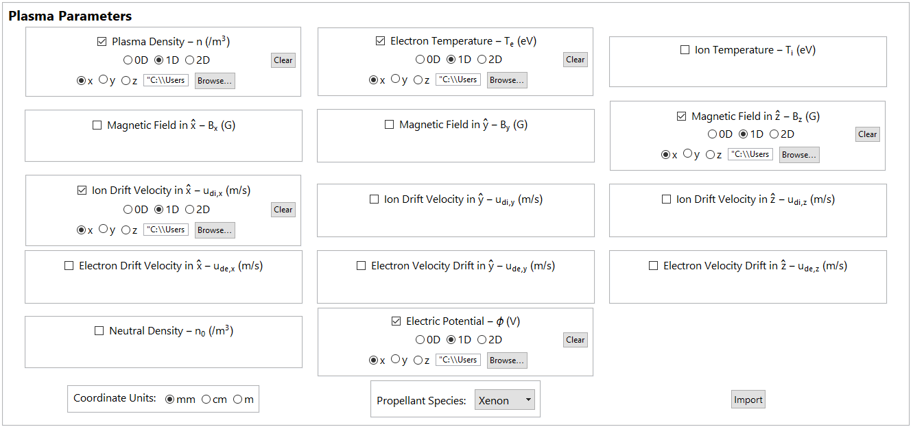
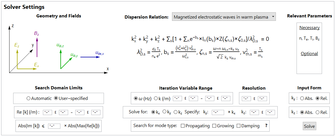
We developed the Plasma Rocket Instability Characterizer (PRINCE), a prototype software tool that numerically solves for the zeros of a user-specified \(\mathcal{D}\) using geometry and plasma parameter data input through a graphical interface (Figures 1 and 2). PRINCE autonomously locates and tracks the zeros of the dispersion relation chosen by the user by applying numerical algorithms based on Cauchy’s Argument Principle and Newton-Raphson’s method. Information about the instabilities found is presented through various data visualization options.
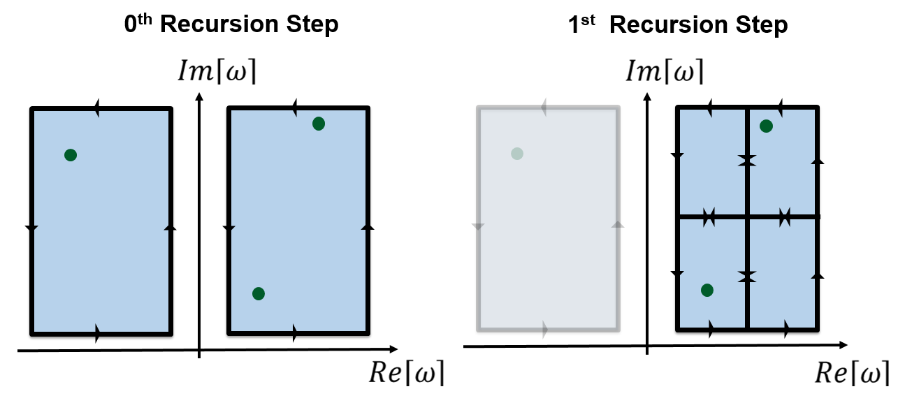
PRINCE finds the zeros (green dots) of \(\mathcal{D}\) using a root-finding algorithm which applies Cauchy’s Argument Principle on grid cells (blue) in the complex plane. If multiple zeros are contained in a cell, a recursive application of the algorithm to subdivided cells resolves the zeros (Figure 3). A separate root-tracking algorithm characterizes the zeros as functions of \(\omega\) or \(\mathbf{k}\). See this paper for full details.
Active Wave Packet Injection Diagnostic
To complement PRINCE’s numerical capabilities, we developed an experimental diagnostic which measures the dispersion relation of a plasma by actively injecting wave packets into the discharge and recording the plasma’s dielectric response. In contrast to techniques like passive probe interferometry or laser-induced fluorescence, the active wave packet injection (AWPI) methodology provides the ability to tailor the harmonic content of the input signal in addition to control over the signal-to-noise ratio of the measurements. The linear dispersion relation can them be measured simultaneously at multiple frequencies.
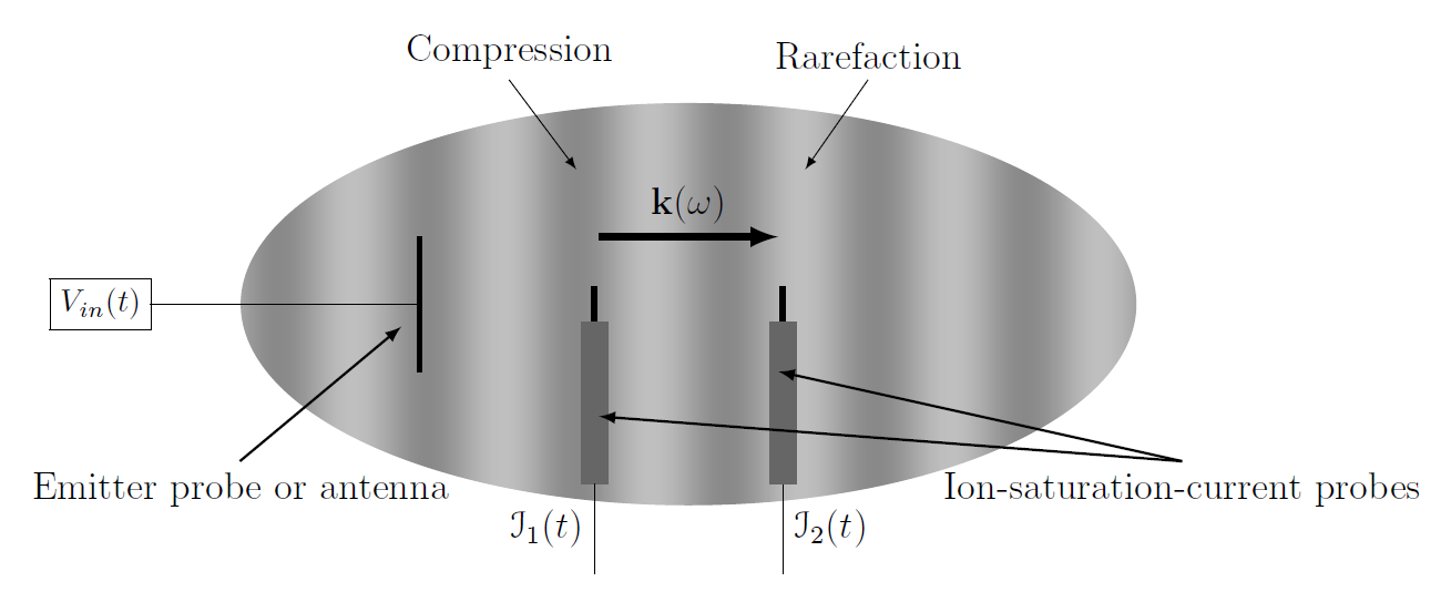
As shown in Figure 4, an emitter probe or antenna injects a wave which travels downstream to receiver probes which record time-dependent ion-saturation-current traces. Frequency-domain analysis involving Welch’s method to estimate power and coherence spectra of these fluctuating currents, which correspond to plasma density compressions and rarefactions induced by the plasma waves, yields the plasma dispersion relation measurement.
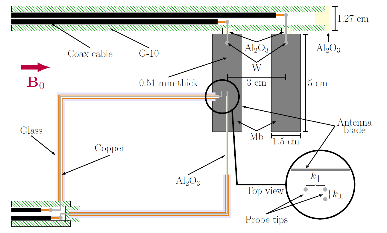
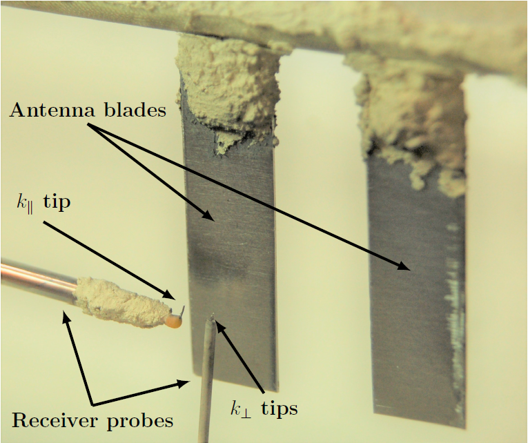
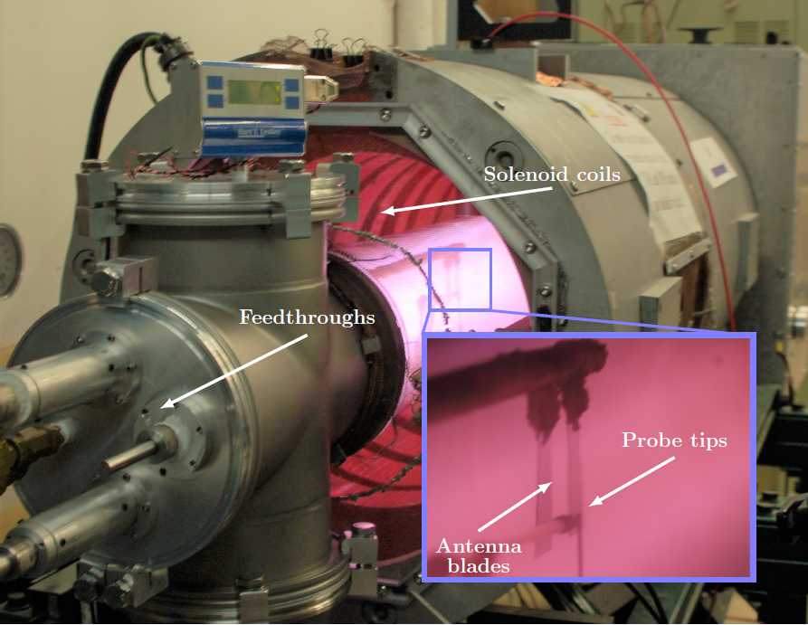
We developed the AWPI diagnostic schematically shown in Figure 5 and photographed in Figure 6. Two molybdenum plates constitute the diagnostic’s antenna while a set of three Langmuir probes serve as receiver probes for measurements of the wavenumber in the directions parallel and perpendicular to the background magnetic field. We used the diagnostic in an experimental study of electrostatic ion-cyclotron (EIC) waves conducted in the 13.56 MHz magnetized RF argon discharge pictured in Figure 7. We measured the dispersion relation of the plasma and found it to agree with the fluid theory predictions.
Publications and Posters
- Plasma Dispersion Relation Measurements through Active Injection of Wave Packets, 36th International Electric Propulsion Conference (2019)
- PRINCE: A Software Tool for Characterizing Waves and Instabilities in Plasma Thrusters, 52nd AIAA/ASME/SAE/ASEE Joint Propulsion Conference (2016)
- Numerical Tool for Evaluating Hall Thruster Stability (Poster)
- Characterizing Plasma Oscillations Using Active Wave Injection (Poster)
Contact
Currently at Princeton:- None
- Sebastián Rojas Mata